How to Add Extra Solar Panels to a Renogy or ECO‑WORTHY Plug‑and‑Play Kit: Step‑by‑Step Wiring, Sizing & Safety Tips
Introduction
The modern off‑grid enthusiast often begins with a starter kit and later discovers the need for additional power. This guide explains how to evaluate energy demand, select appropriate extension cables, and integrate extra panels into either a Renogy or ECO‑WORTHY system. Readers will understand why proper sizing prevents voltage drop and how weather‑proof connectors protect long‑term installations. By following the procedures, one can increase daily generation by up to 200 % while maintaining safety and warranty compliance.
What You'll Need
- Existing plug‑and‑play kit (Renogy 100W Solar Starter Kit or ECO‑WORTHY 200W Solar Panel Kit)
- Additional solar panel(s) matching the voltage of the original kit
- Geosiry 10AWG Solar Extension Cable 3ft – 3 ft, 10 AWG, IP67 waterproof connectors (price $12.34, rating 4.8/5)
- BougeRV 10AWG Solar Extension Cable 20ft – 20 ft, tin‑coated copper, UV‑resistant (price $29.99, rating 4.7/5)
- MC4 compatible connectors if panel leads differ
- Inline fuses appropriate for the system current (e.g., 30 A)
- Wire strippers, crimping tool, and a multimeter for verification
- Mounting hardware (brackets, zip ties) suitable for the vehicle or structure
Step‑by‑Step Instructions
Step 1: Assess Power Requirements
Begin by calculating the total daily energy consumption of all loads that will be powered by the solar array. Multiply each device's amp‑hour rating by the number of hours of use, then sum the results to obtain a target watt‑hour figure. Compare this figure with the existing kit's average output – the Renogy 100W kit generates approximately 500 Wh per day under optimal conditions, while the ECO‑WORTHY 200W kit can deliver up to 800 Wh per day. If the target exceeds the current output by a substantial margin, additional panels are justified.
Next, verify that the charge controller can accommodate the increased current. The Renogy Wanderer 30A PWM controller supports up to 400 W of solar input, and the ECO‑WORTHY 30A PWM controller has a similar rating. Ensure that the combined wattage of the original and new panels does not surpass the controller's maximum input. This precaution protects the controller from overheating and preserves the manufacturer's warranty.
Step 2: Choose Compatible Panels
Select panels that match the voltage range of the existing kit – typically 12 V nominal for both Renogy and ECO‑WORTHY systems. Panels with monocrystalline cells and efficiencies above 20 % are recommended because they occupy less roof area while delivering higher power. For example, a 100 W monocrystalline panel pairs well with the Renogy starter kit, whereas a second 100 W panel complements the ECO‑WORTHY 200W kit without altering the system architecture.
When purchasing, confirm that the panel includes MC4 connectors, as these will mate directly with the extension cables provided in the next step. Panels lacking MC4 connectors require adapter kits, which add complexity and potential points of failure.
Step 3: Determine Cable Length and Gauge
Voltage drop becomes significant when long runs are required. A 10 AWG cable, such as the Geosiry 10AWG Solar Extension Cable 3ft, limits drop to less than 2 % over short distances, making it ideal for rooftop installations where the controller sits nearby. For runs exceeding ten feet, the BougeRV 10AWG Solar Extension Cable 20ft provides the same gauge with superior conductivity due to its tin‑coated copper construction.
Both cables feature IP67 waterproof rings and built‑in locks, ensuring a secure, weather‑proof connection that complies with outdoor installation standards. The dual‑jacket design (PVC and PPO for Geosiry, XLPE for BougeRV) also resists UV degradation, extending service life in harsh sun exposure.
Step 4: Prepare the Wiring
- Disconnect the existing solar panel from the charge controller to prevent accidental short circuits.
- Strip ½ inch of insulation from the bare end of the extension cable using a wire stripper.
- If the new panel has a bare lead, attach an MC4 male connector using a compatible crimping tool; otherwise, use the factory‑installed MC4 connector.
- Secure the connector onto the stripped end of the extension cable, ensuring the lock mechanism clicks into place.
After the connectors are attached, route the cable along the mounting surface, securing it with zip ties at intervals of no more than 12 inches. This practice prevents movement that could stress the connectors during vibration, especially on vehicles.
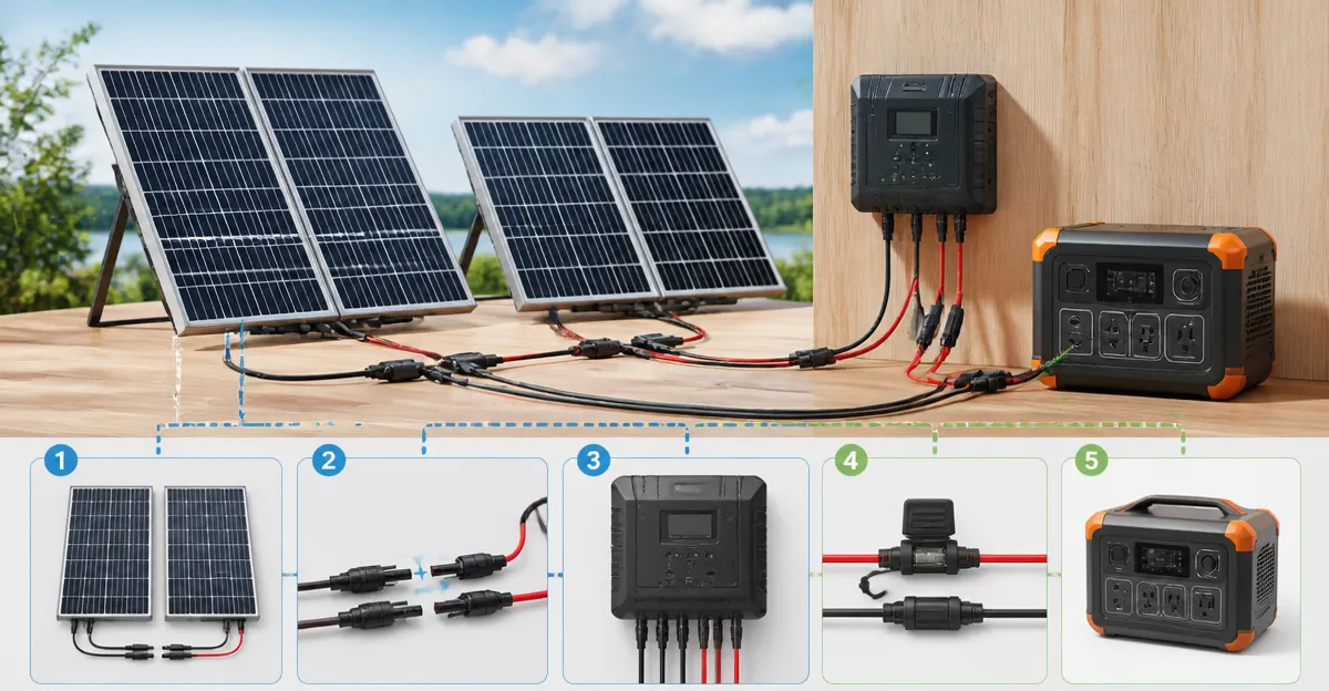
Step 5: Connect Panels in Parallel or Series
For 12 V systems, panels are typically wired in parallel to maintain the nominal voltage while increasing current. Parallel wiring involves connecting all positive leads together and all negative leads together before feeding the combined pair into the controller. If a 24 V configuration is desired, panels can be wired in series, doubling the voltage while keeping current constant; the ECO‑WORTHY kit explicitly supports series connections.
When wiring in parallel, use a Y‑branch connector (often included with the kits) to merge the leads safely. Verify that the combined current does not exceed the controller's rated input – for a 30 A controller, a total current of 25 A provides a safe margin.
Step 6: Install Inline Fuses
Place an appropriately rated inline fuse on the positive lead between the panels and the charge controller. A 30 A fuse protects the wiring against short circuits and aligns with the controller's maximum input. Install the fuse as close to the panel array as possible to isolate faults quickly.
After installing the fuse, reconnect the positive and negative leads to the controller, ensuring the lock mechanisms are fully engaged. The waterproof ring on each connector prevents moisture ingress, which is critical for long‑term reliability in rainy or dusty environments.
Step 7: Verify Polarity and Perform a Voltage Test
Before energizing the system, use a digital multimeter to confirm correct polarity. Measure the voltage between the positive and negative leads at the controller input; a reading of 18‑22 V under full sun indicates proper connection for a 12 V nominal system. If the voltage is significantly lower, re‑examine the cable connections for loose or reversed polarity.
Once the voltage is verified, re‑connect the controller to the battery, then observe the charge controller's display. The Renogy Wanderer controller will show panel voltage, current, and battery status; the ECO‑WORTHY controller offers a similar LCD readout. Ensure that the controller indicates charging mode rather than error or fault status.
Step 8: Secure and Seal All Connections
Apply a marine‑grade silicone sealant around each connector housing to reinforce the IP67 rating, especially in environments with frequent rain or sea spray. Tighten the lock tabs on the male connectors until they resist manual pull‑out. Finally, route any excess cable back into the vehicle or enclosure, securing it with cable clamps to avoid chafing.
Perform a final visual inspection to confirm that no bare wires are exposed and that all mounting hardware is tightened to manufacturer specifications. This step reduces the risk of abrasion‑induced failures during travel.
Tips & Pro Tips
- Mount panels at a tilt angle that matches the latitude of the installation site to maximize sun exposure throughout the year.
- Use a solar tracker or adjustable brackets if the installation platform permits; the Renogy kit includes tilt mounts that have proven effective in mountainous terrain.
- When expanding beyond 200 W, consider upgrading to a Maximum Power Point Tracking (MPPT) controller for higher efficiency, though the PWM controllers included in both kits remain reliable for modest expansions.
- Label each cable with its length and purpose; this practice simplifies future troubleshooting and upgrades.
- Periodically clean panel surfaces and connector rings to maintain optimal light transmission and electrical contact.
Troubleshooting
Problem: The controller shows zero current despite bright sunlight.
Solution: Verify that the inline fuse is not blown, check polarity, and ensure the MC4 connectors are fully locked. Replace any damaged cable using the Geosiry 3‑ft or BougeRV 20‑ft extension as needed.
Problem: Voltage drops below 12 V under load.
Solution: Measure the resistance of the extension cable; if the drop exceeds 0.5 Ω, replace the run with a shorter or higher‑gauge cable. The 10 AWG BougeRV cable minimizes loss over longer distances.
Conclusion
By following this structured approach, one can safely augment a Renogy or ECO‑WORTHY plug‑and‑play solar kit with additional panels, thereby increasing daily energy production without compromising system integrity. Proper assessment of power needs, selection of weather‑proof 10 AWG extension cables, and diligent verification of polarity and voltage ensure a reliable, expandable solar solution. Readers are encouraged to apply these techniques to future upgrades, confident that the system will continue to operate efficiently for years to come.
Products Mentioned in This Guide
Frequently Asked Questions
Can I mix Renogy and ECO‑WORTHY panels in the same plug‑and‑play system?
No; all panels must have the same voltage and current specifications to avoid mismatched strings and warranty issues.
What gauge of extension cable should I use for adding extra panels?
Use 10 AWG cable for runs up to 10 ft to keep voltage drop below 3 % and maintain efficient charging.
How do I calculate the maximum number of panels I can add?
Multiply the kit’s controller voltage rating by its maximum input current, then divide by the voltage and current of each additional panel.
Do I need waterproof connectors for outdoor panel extensions?
Yes; IP67‑rated connectors protect against moisture and corrosion, ensuring long‑term reliability.
Will adding panels void the original kit’s warranty?
Adding compatible panels with proper wiring and connectors does not void the warranty, but using non‑approved components may.